To apply a photoresist coating, a spin-coater is essential as it ensures a uniform thin film of liquid coating. However, spin-coaters can be quite bulky and expensive, which poses a challenge given my research objectives for a setup that is neither cumbersome nor costly.
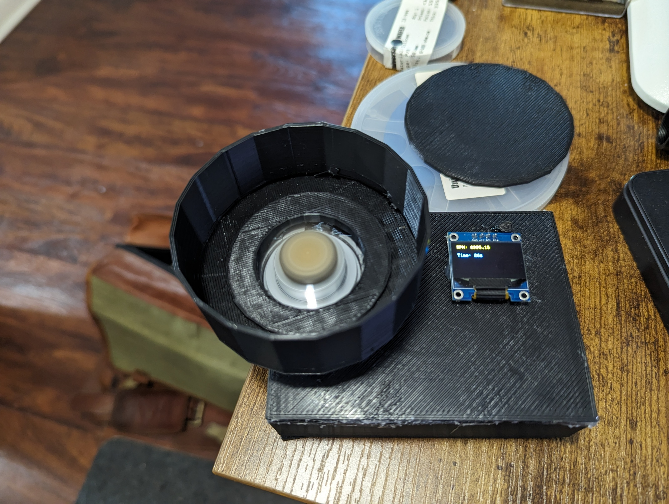
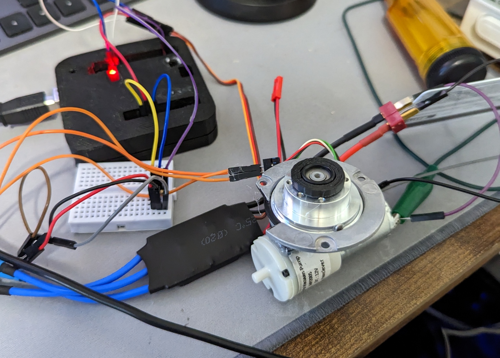
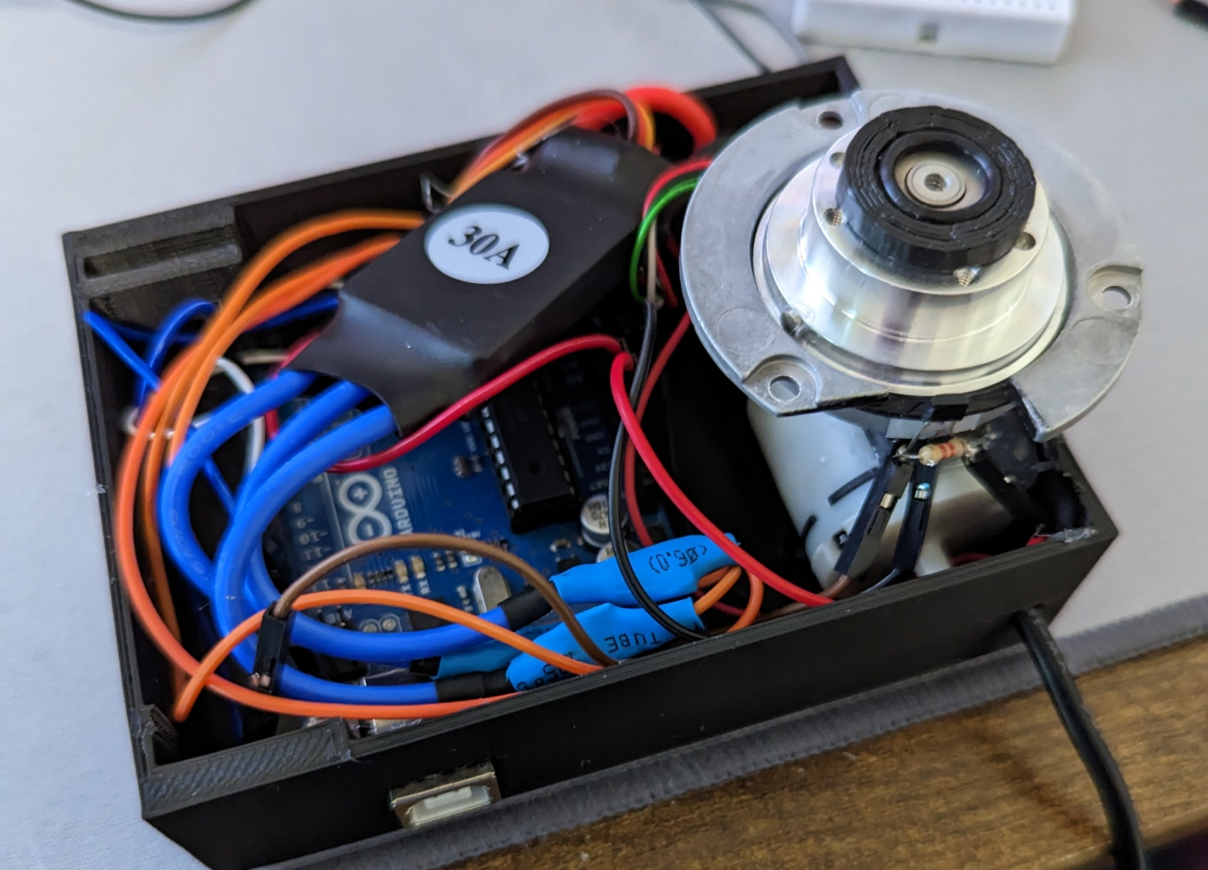
A rudimentary PC fan with double-sided tape could serve as a spin-coater, but it lacks the functionality of a more sophisticated system. For this endeavor, I repurposed an old hard drive motor. These motors are three-phase, with the coils encircling the center, which conveniently allows for a vacuum hole to be drilled through. An aquarium air pump is attached to the opening at the bottom of the hard drive motor to create a vacuum for processing small samples. To enhance the vacuum seal, the top of the hard drive motor features an o-ring housed within a 3D printed cap. A quadcopter driver is employed to control the motor, offering a cost-effective and well-supported platform for easy control. Commands are sent to the quadcopter driver board via an Arduino. To monitor the RPM, a magnet is affixed to the side of the hard drive, which interacts with a Hall sensor.
The RPM is managed through a feedback loop to maintain the desired speed and runtime. RPM primarily influences thickness, with the duration being a secondary factor. The spin-coater is programmed to utilize a swift ramp rate to minimize edge bead, which is crucial for small samples. The RPM and remaining time are displayed on a screen, making the unit standalone, requiring only a power cord. A case and a spin-coating bowl were 3D printed to encase the unit and catch excess photoresist, respectively. The bowl can be lined with aluminum foil for extended use or replaced as needed.
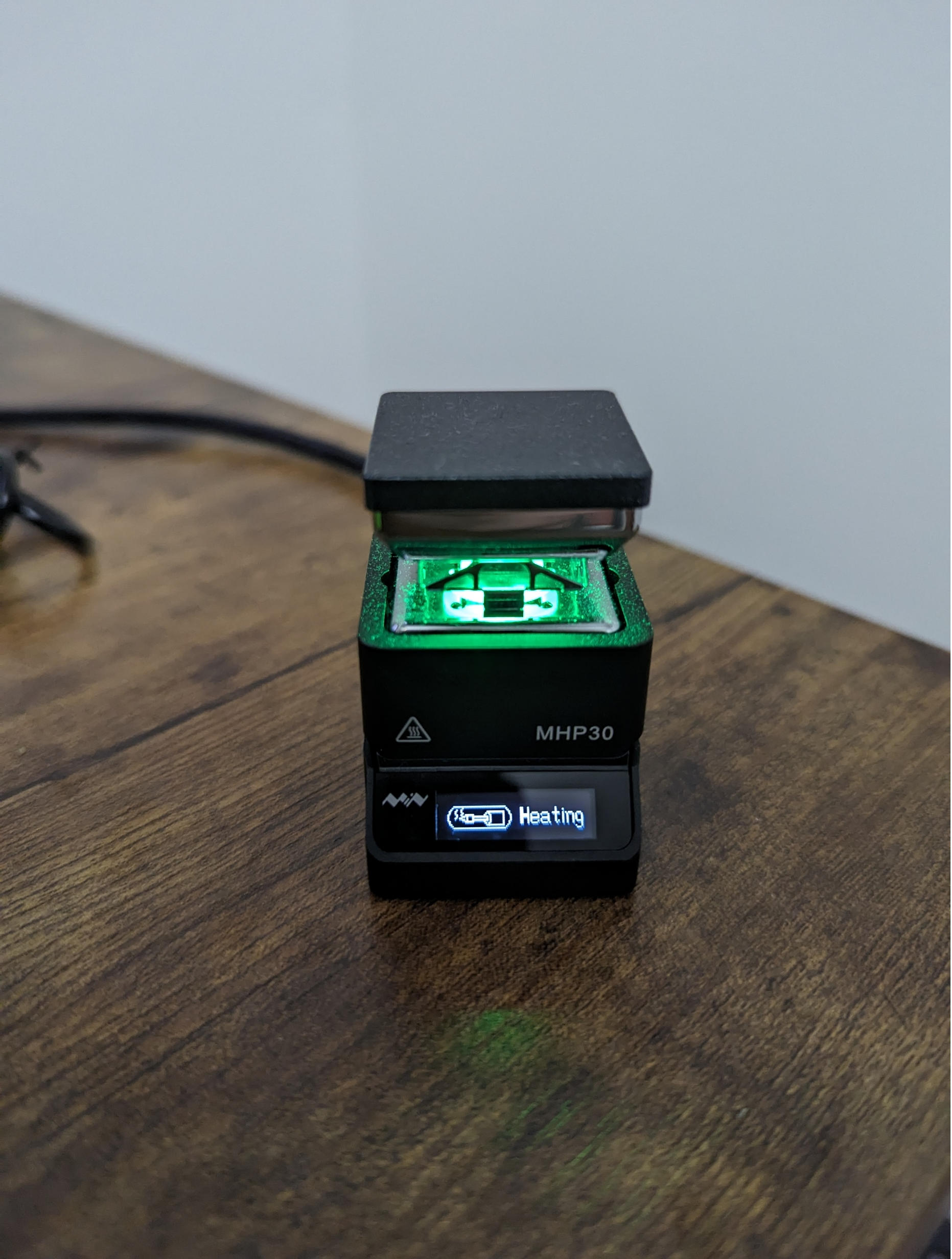
Post-application baking is carried out on a compact 1" MHP30 USB-C hotplate, which offers excellent temperature control for small sample sizes. Although the photoresist coating process should be highly repeatable, knowing the photoresist coating thickness is vital for both exposure and etching steps, especially when developing a new process. For optically semi-transparent thin films, thin film interference between surfaces is utilized to ascertain the film thickness.
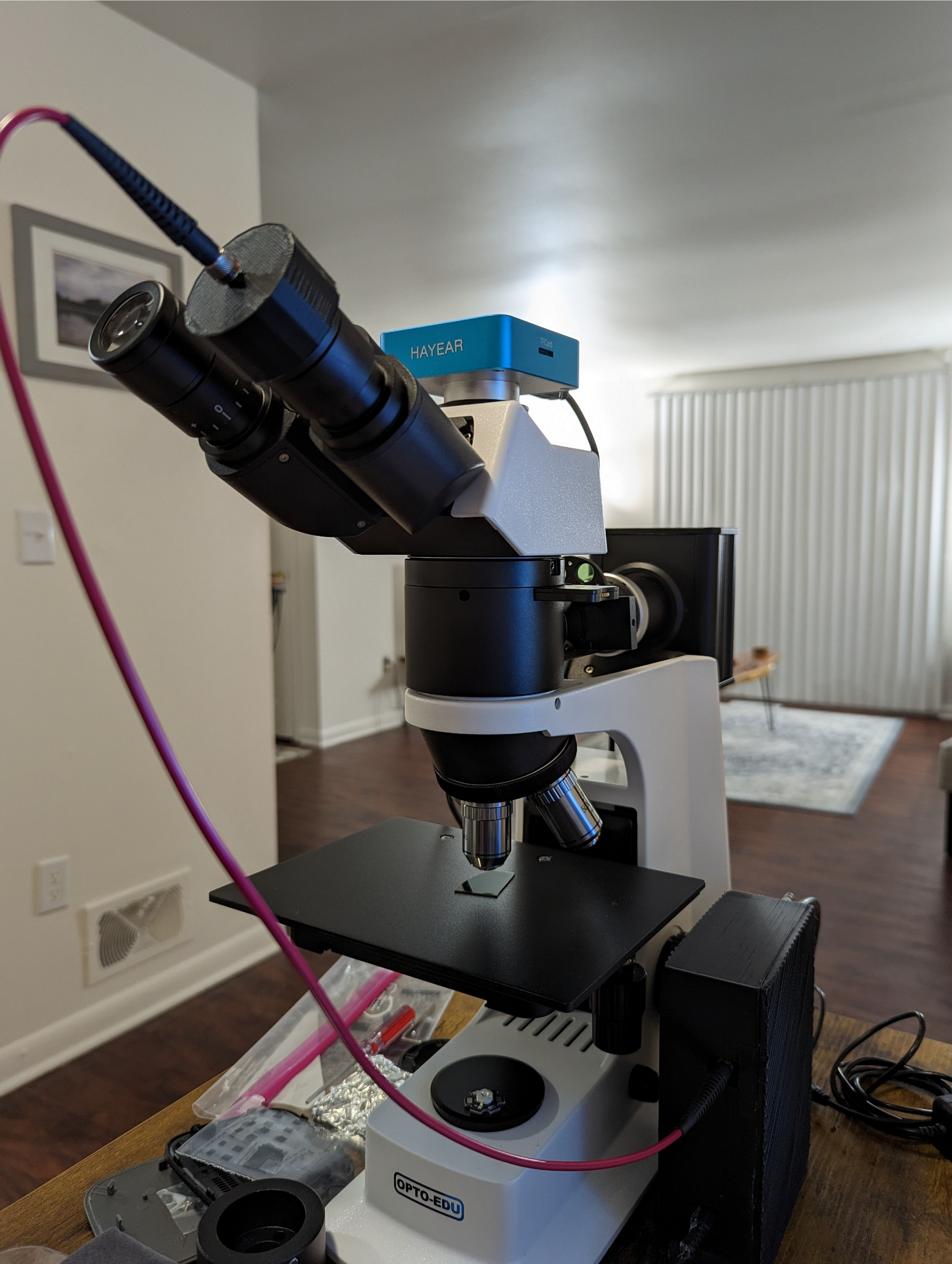
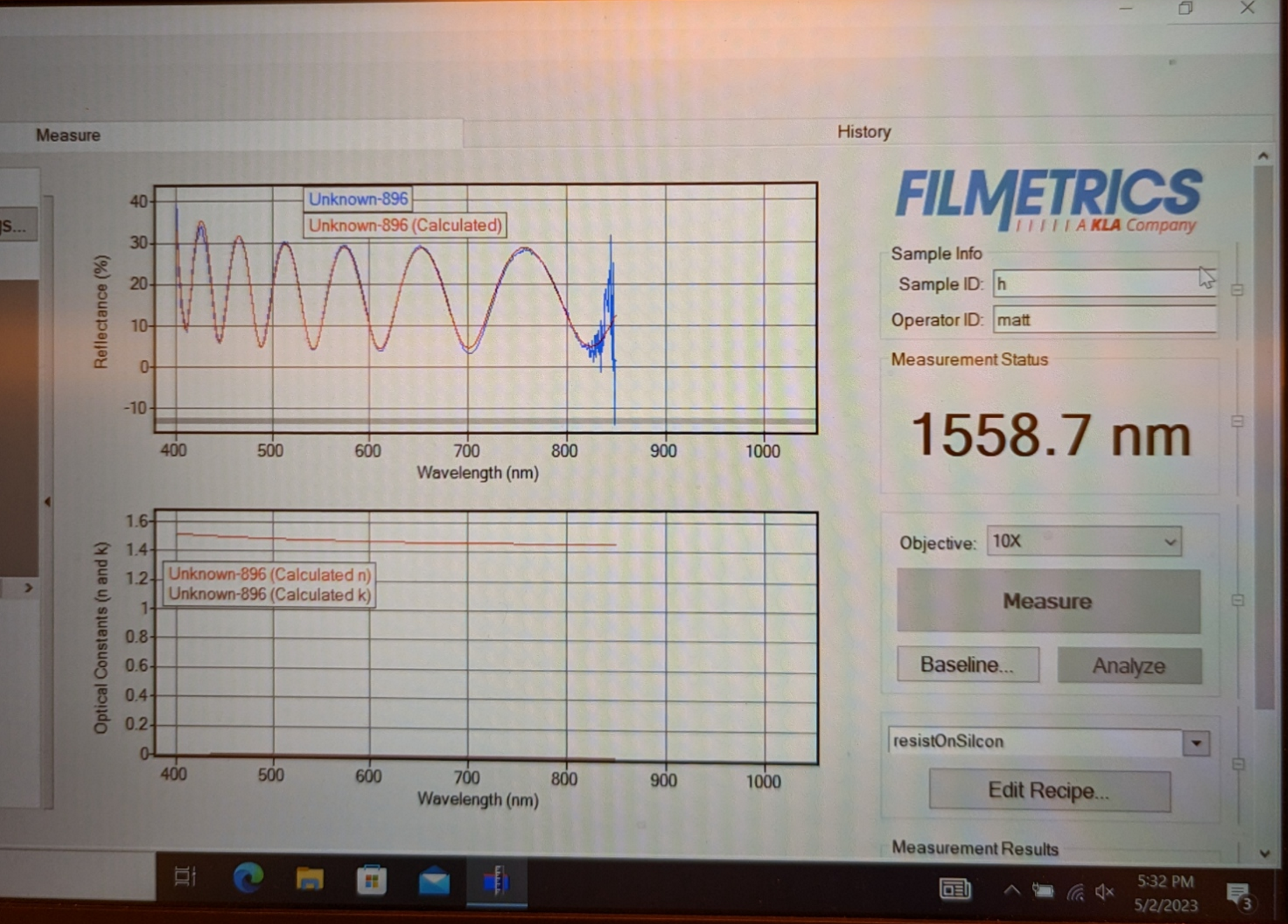
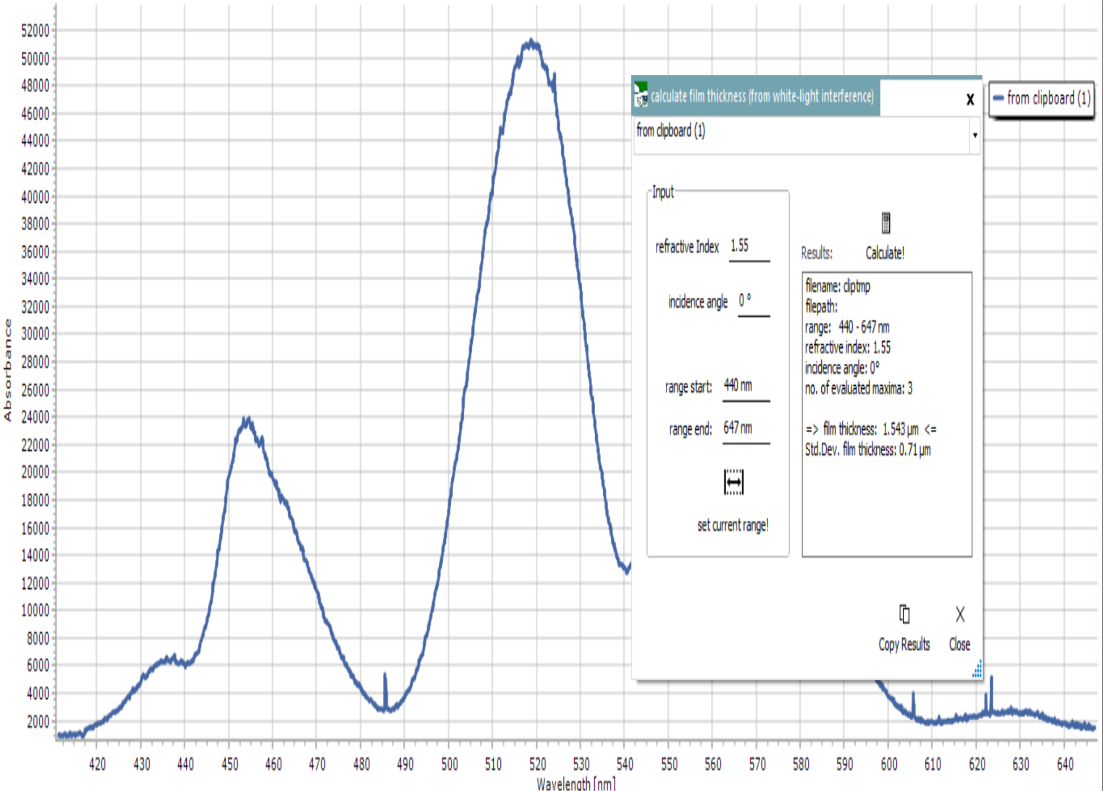
Filmeterics offers several systems for optical thickness characterization of thin films, but they tend to be bulky and expensive for a home lab setup. In lieu of these systems, a basic spectrometer is used with a 3D printed adapter to observe through a microscope eyepiece, employing a white LED light source. Thin film interference can be distinctly observed and recorded in contrast to the original light spectra. The interference pattern data is used to calculate thickness either manually or using Spectragryph, a free optical spectroscopy software. A coating of AZ1512 is compared between the Filmetrics system and Spectragryph, revealing a close alignment in results. This method of optically characterizing transparent thin films extends beyond photoresists to other materials such as dielectrics, proving to be a highly valuable technique. The combination of spin coating and film characterization is achieved at a low cost, thereby facilitating semiconductor fabrication.
Future plans for this system include homebrew transistor fabrication and research on wide band-gap materials.
Spin Coater Code
#include <Servo.h>
#include <Wire.h>
#include <Adafruit_GFX.h>
#include <Adafruit_SSD1306.h>

#define SCREEN_WIDTH 128
#define SCREEN_HEIGHT 64

Adafruit_SSD1306 display(SCREEN_WIDTH, SCREEN_HEIGHT, &Wire, -1);

// Set up motor
Servo BMotor;
const int B_Motor = 13;

// Set up hall sensor
const int hall_pin = 2;
const float hall_thresh = 10.0;
float hall_count = 0.0;
bool on_state = false;

// Set up RPM measurement timeout
const unsigned long rpm_timeout = 500000UL; // 0.5 seconds

// PID constants
const float Kp = 0.2; // Proportional gain

// Target RPM
const float target_rpm = 3000;

// Measure RPM and display remaining time
void measureRPM(unsigned long remaining_time) {
  unsigned long start_time = micros();
  while (hall_count < hall_thresh && micros() - start_time < rpm_timeout) {
    if (digitalRead(hall_pin) == LOW) {
      if (on_state == false) {
        on_state = true;
        hall_count += 0.5;
      }
    } else {
      on_state = false;
    }
  }
  float end_time = micros();
  float time_passed = (end_time - start_time) / 1000000.0;
  float rpm_val = (hall_count / time_passed) * 60.0;
  Serial.print("RPM: ");
  Serial.println(rpm_val);

  // Display RPM and remaining time on SSD1306 display
  display.clearDisplay();
  display.setTextSize(1);
  display.setTextColor(SSD1306_WHITE);
  display.setCursor(0, 0);
  display.print("RPM: ");
  display.println(rpm_val);

  display.setCursor(0, 10);
  display.println();
  display.print("Time: ");
  display.print(remaining_time / 1000);
  display.println("s");

  display.display(); // Update the display

  // Reset hall count and on state variables for next measurement
  hall_count = 0.0;
  on_state = false;

  // Adjust motor speed based on RPM feedback
  float error = target_rpm - rpm_val;
  int motor_speed = BMotor.readMicroseconds() + (int)(Kp * error);
  if (motor_speed < 1000) {
    motor_speed = 1000;
  } else if (motor_speed > 2000) {
    motor_speed = 2000;
  }
  BMotor.writeMicroseconds(motor_speed);
}

void setup() {
  delay(10000);
  Serial.begin(115200);
  BMotor.attach(B_Motor);
  BMotor.writeMicroseconds(1000);
  delay(2000);
  BMotor.writeMicroseconds(1400);
  delay(500);
  BMotor.writeMicroseconds(1450);
  delay(500);
  BMotor.writeMicroseconds(1700);
  delay(2000);
  pinMode(hall_pin, INPUT);

  // Initialize the SSD1306 display
  display.begin(SSD1306_SWITCHCAPVCC, 0x3C); // Address 0x3C for 128x64
  display.clearDisplay();
  display.setTextColor(SSD1306_WHITE);
  display.setTextSize(1);
}

void loop() {
  unsigned long start_time = millis(); // Start time of loop
  unsigned long time_limit = 30000;    // 30 seconds
  while (millis() - start_time < time_limit) {
    // Calculate remaining time
    unsigned long elapsed_time = millis() - start_time;
    unsigned long remaining_time = time_limit - elapsed_time;

    // Measure RPM and display RPM and remaining time
    measureRPM(remaining_time);
  }
  Serial.println("Loop completed.");
  BMotor.writeMicroseconds(0); // Stop motor
  while (true)
    ; // Halt program execution
}